Height Adjustment and Height Measurement
On each pin are a total of 8 (sweep) or 16 (sculling) 1.6mm black plastic washers which are used for fine-tuning the height and adjusting the differential distance of the starboard over the port oarlock height. A normal setting would be about 160mm +/- 15mm (6 ½” +/- ½”) from the lowest part of the seat. For scullers, the oarlock height of the leading hand, which will be closest to you, should be about 6 or 12 mm (1/4″ to ½”) lower to provide some knuckle clearance. For sculling novices start with 12mm. or more clearance and as your technique improves, decrease the clearance. For sweep rowing, the height will be about 170 mm +/- 15 mm from the lowest part of the seat.
Using Special Tools to Measure Symmetry & Relative Height of Riggers/Locks

Pitch: Pitch is the measurement of degrees that the face of the oarlock is inclined from the vertical. Pitch compensates for the flexibility of the oar/rigger system and the imbalance of forces resulting in the blade attempting to dive. The result is that an oar with too little pitch will go deep and be difficult to extract at the end of the stroke. Because the pitch required is dependent on how stiff the system is you must estimate how stiff your equipment is as a starting point. Many years ago when all boats and oars were made of wood we used about 7 – 8 degrees of the pitch with some in the oar and some in the lock. In some countries like Germany that is still the case. Today with the stiffer composite boats, carbon oars, and riggers, the pitch of 4 degrees is molded into the face of the oarlock and the pin that the lock swivels about is set at zero degrees in all directions. If the oar, scull, or rigger is constructed correctly all the extra pitch bushings except for the 4-degree pair that comes with modern oarlocks are seldom used. Most oars and sculls are manufactured well within ½ degree of 0-degree pitch, except those built for the German market which uses 3 degrees. Carbon tubular riggers have pins set at 0 degrees with pitch inserts used to decrease the molded-in 4 degrees to 2 or 3 degrees. This is because the system is very stiff. On the other hand, a recreational or club single with a wing rigger may use pitch inserts to increase the pitch to 5 or 6 degrees. To determine if you need to correct pitch you must row the boat and observe how the oar tracks through the water. Assuming that you row correctly and have the oar seated against the lock face the oar blade should be buried completely and stay at a constant depth and come out cleanly at the finish. If the result of a test row indicates a pitch adjustment then try different degrees of pitch inserts in pairs and repeat the test to see if it makes a difference.
Three Types of Pitch Gauges
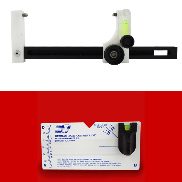 A pitch gauge is used to check if the riggers have been manufactured correctly or if anything has moved. A pitch gauge is a bubble-type inclinometer. Many types are available and they all work the same way. With the boat strapped down firmly in stretchers, the movable level of the pitch meter is set to level in the bow to stern direction using either the gunnels or the bottom of the hull near the midpoint.
Strapping the Boat Down Firmly

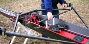
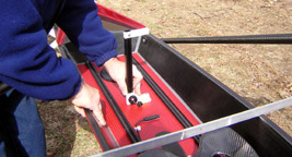
Using a Pitch Gauge to Level the Boat in All Directions
Once the bubble is set to indicate 0 degrees the pitch gauge is then placed 90 degrees across the tracks and the boat adjusted so that you now have a 0-degree reference plain in all directions.
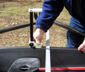
Leveling the Boat in the Fore-Aft Direction – Leveling the Boat Side-to-Side
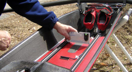
Using the Pitch Gauge with Special Bolt with Conical Indents
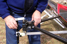
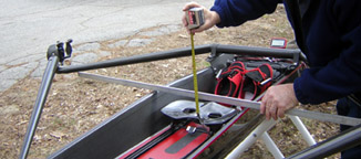
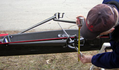
Rigger Spread or Span: Spread is the distance between the centerlines of the lock pins of sculling boats. Span is the distance between the centerline of the boat and the centerline of the pin and sweep boats. For sculling boats, the spread ranges between 156 and 163cm with most common being 160cm. Sweep boats will range between 81 to 86cm. To assure equal leverage a measurement from the port side track to the starboard lock and vise-versa is made. The actual measurement number is not noted, but must be identical at all positions, both port and starboard so that the boat will pull straight.
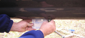
Checking the Spread with a Tape Measure and Related Measurements
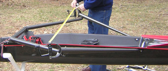
Also, measure the distance from the centerline on each pin to the outside edge of the opposite track or opposite gunnel. Also, measure the centerline of the pin to number clip to compare fore and aft dimensions from side to side. You can tape, the tape-measure end into the number clip slot, to make this measurement done more easily.